вступ
This manual provides detailed instructions for the Wishiot L298N Motor Driver Board Control Module and the accompanying TT Motor Kit. This kit is designed for use in various robotics and DIY electronics projects, compatible with platforms such as Arduino, Raspberry Pi, and ESP32-CAM. Please read these instructions carefully before setup and operation to ensure proper functionality and safety.
Продукт закінченийview
L298N Motor Driver Module

The L298N Motor Driver is a dual H-bridge module capable of driving two DC motors or one stepper motor. It features a robust L298N chip. The image above illustrates the pinout, including connections for Motor A, Motor B, power supply (+12V, GND, +5V), and control inputs (Input 1-4, Channel-A Enable, Channel-B Enable).
- Чіп: L298N
- Logical Voltage: 5V
- Drive Voltage: 5В-35В
- Logical Current: 0 мА-36 мА
- Струм приводу: 2A (MAX single bridge)
- Максимальна потужність: 25 Вт
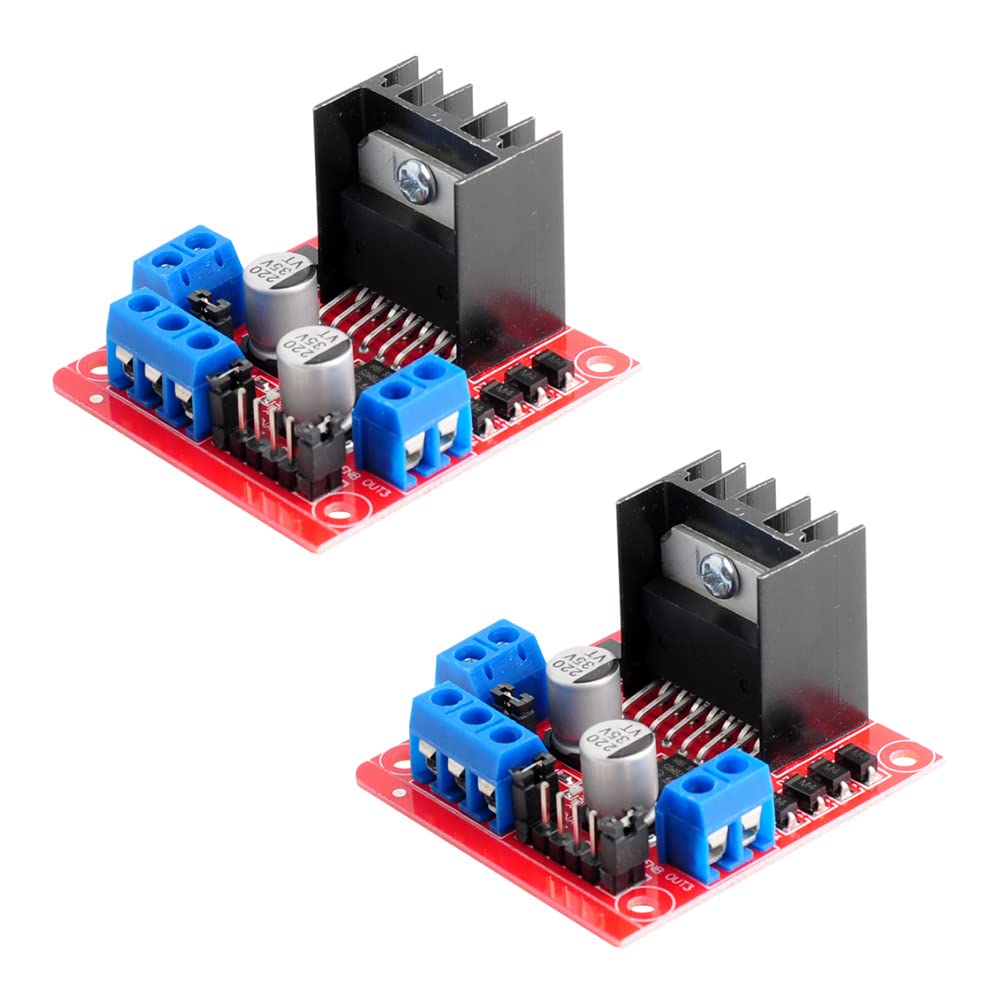
This image shows two L298N motor driver modules, highlighting their compact design with integrated heatsinks and terminal blocks for easy wiring.
DC Gearbox TT Motor
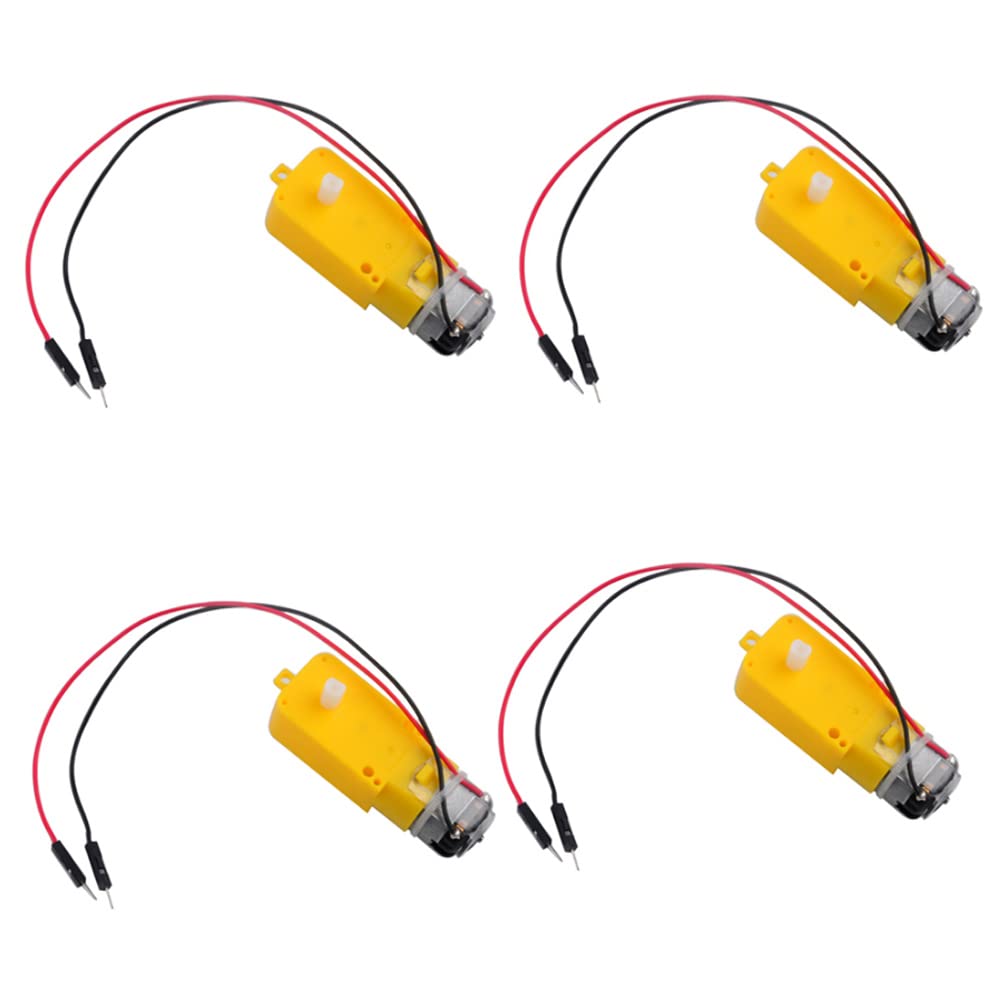
The TT DC Gearbox Motors are compact, dual-shaft motors with a gear reduction ratio of 1:48. They come pre-soldered with 2P male Dupont wires for convenient connection to breadboards or terminal blocks. The image displays four such motors.
- Номінальний випtage: 3~6В
- Continuous No-Load Current: 150mA +/- 10%
- Min. Operating Speed (3V): 90+/- 10% RPM
- Min. Operating Speed (6V): 200+/- 10% RPM
- Крутний момент: 0.15Nm ~0.60Nm
- Stall Torque (6V): 0.8 кг.см
- Коефіцієнт передачі: 1:48
- Розміри корпусу: 70 x 22 x 18 мм
- Wires Length: 200 мм 28 AWG

This diagram provides the physical dimensions of the TT motor, including its length, width, height, and the 8mm length of each plastic dual shaft. The yellow shell can be modified if a shorter shaft is required.
Інструкції з налаштування
Follow these steps to correctly set up your L298N motor driver and TT motors.
- Підключення двигунів: Connect the TT motors to the 'MOTOR A' and 'MOTOR B' output terminals on the L298N board. Each motor has two wires; connect one to OUT1/OUT2 for Motor A and the other to OUT3/OUT4 for Motor B.
- Джерело живлення:
- Connect your main motor drive voltage (5V-35V) to the '+12V' terminal (despite the label, it accepts up to 35V).
- Connect the ground of your power supply to the 'GND' terminal.
- The L298N module has a built-in 5V regulator. If your drive voltage is 7V-12V, the 5V output can be used to power your logic circuit (e.g., Arduino). If your drive voltage is above 12V, it is критичний to use an external 5V logic supply to power the '+5V' terminal and remove the 5V enable jumper, otherwise, the onboard voltage stabilizing chip may be damaged.
- Logic Control Connections: Connect your microcontroller's digital output pins to the L298N's 'Input 1', 'Input 2', 'Input 3', 'Input 4', 'Channel-A Enable', and 'Channel-B Enable' pins.
- Enable Jumpers: Ensure the 'Channel-A Enable' and 'Channel-B Enable' jumpers are in place if you intend to control motor speed via PWM on the enable pins. If you are not using PWM for speed control, these jumpers should remain connected to provide full power to the motors when inputs are active.

This diagram illustrates a typical wiring example for connecting two TT motors to the L298N driver, controlled by a microcontroller (ESP32-CAM shown as an example, not included) and powered by a 5V source (power bank shown as an example, not included). The motors themselves are for display purposes in this diagram.
Інструкція з експлуатації
The L298N module uses an H-bridge configuration to control the direction and speed of DC motors. Each motor (A and B) is controlled by two input pins and one enable pin.
Motor Direction Control
To control the direction of Motor A (connected to OUT1 and OUT2), manipulate 'Input 1' and 'Input 2':
- Вперед: Input 1 = HIGH, Input 2 = LOW
- Зворотний: Input 1 = LOW, Input 2 = HIGH
- Stop/Brake: Input 1 = LOW, Input 2 = LOW (or HIGH, HIGH for brake)
Similarly, for Motor B (connected to OUT3 and OUT4), use 'Input 3' and 'Input 4'.
Motor Speed Control (PWM)
To control motor speed, connect a Pulse Width Modulation (PWM) signal from your microcontroller to the 'Channel-A Enable' (for Motor A) or 'Channel-B Enable' (for Motor B) pins. The duty cycle of the PWM signal will determine the average voltage supplied to the motor, thus controlling its speed. Ensure the corresponding enable jumper is removed if using external PWM.
Технічне обслуговування
Proper maintenance ensures the longevity and reliable operation of your motor driver and motors.
- Тримати в чистоті: Regularly inspect the modules for dust or debris and clean gently with a soft, dry brush or compressed air.
- Уникайте перегріву: Ensure adequate ventilation around the L298N module, especially during prolonged operation or when driving high currents. The heatsink helps dissipate heat, but extreme conditions can still lead to overheating.
- Перевірте підключення: Periodically verify that all wire connections are secure and free from corrosion. Loose connections can lead to intermittent operation or damage.
- Джерело живлення: Завжди використовуйте стабільне джерело живлення в межах зазначеної гучностіtage ranges. Over-voltage can permanently damage the L298N module.
Усунення несправностей
Якщо у вас виникли проблеми, зверніться до наступних порад щодо усунення несправностей:
- Двигун не обертається:
- Check all power connections to the L298N module and ensure the power supply is active and within the specified voltagе діапазон.
- Verify that the motor wires are correctly connected to the output terminals (OUT1/OUT2, OUT3/OUT4).
- Ensure the logic control signals (Input 1-4) are correctly applied and that the enable jumpers are in place (or PWM signal is active if using speed control).
- Test the motors directly with a known good power source to confirm they are functional.
- Motor Spins in Wrong Direction:
- Reverse the polarity of the motor's connection to the L298N output terminals (e.g., swap OUT1 and OUT2 wires).
- Alternatively, reverse the logic signals (e.g., if Input 1 was HIGH and Input 2 was LOW for forward, try Input 1 = LOW and Input 2 = HIGH).
- L298N Module Gets Hot:
- This is normal under load, but excessive heat indicates potential issues. Ensure the heatsink is properly attached.
- Check if the motor current draw exceeds the 2A per bridge limit.
- Verify that the drive voltage is not excessively high for the load.
- No 5V Output from L298N (if using internal regulator):
- If your motor drive voltage is above 12V, you повинен use an external 5V logic supply and remove the 5V enable jumper. Failure to do so can damage the onboard voltagрегулятор.
Технічні характеристики
| компонент | Специфікація | Значення |
|---|---|---|
| L298N Motor Driver | Чіп | L298N |
| Logical Voltage | 5V | |
| Drive Voltage | 5В-35В | |
| Logical Current | 0 мА-36 мА | |
| Drive Current (Max Single Bridge) | 2A | |
| Максимальна потужність | 25 Вт | |
| DC Gearbox TT Motor | Номінальний випtage | 3~6В |
| Continuous No-Load Current | 150mA +/- 10% | |
| Min. Operating Speed (3V) | 90+/- 10% RPM | |
| Min. Operating Speed (6V) | 200+/- 10% RPM | |
| Крутний момент | 0.15Nm ~0.60Nm | |
| Stall Torque (6V) | 0.8 кг.см | |
| Передаточне число | 1:48 | |
| Розміри кузова | 70 x 22 x 18 мм | |
| Wires Length | 200 мм 28 AWG | |
| Загальний | Бренд | Wishiot |
| Назва моделі | L298N TT motor | |
| матеріал | пластик | |
| Вага товару | 170 Grams (approx. for kit) | |
| ASIN | B09T2N6R53 |
Підтримка
For any questions or technical assistance regarding your Wishiot L298N Motor Driver and TT Motor Kit, please contact Wishiot directly. You can typically find a 'Contact Seller' or 'Ask a question' option on the product's purchase page or by visiting the Wishiot store page on the platform where you made your purchase.


