
1. Вступ
The EC Buying STM32F103RCT6 Core Board is a versatile development board designed for embedded systems projects. It features the STM32F103RCT6 microcontroller, offering a 72MHz main frequency, 256KB Flash memory, and 48KB SRAM. This board provides extensive connectivity with 45 IO ports, a dedicated SPI LCD interface, and various debugging options, making it suitable for learning and advanced development applications.
2. Ключові характеристики
- Висока продуктивність: Equipped with an STM32F103RCT6 microcontroller, operating at a 72MHz main frequency, 256KB Flash, and 48KB SRAM.
- Розширений ввід/вивід: Features 45 accessible IO ports for diverse project requirements.
- SPI LCD Interface: Dedicated FPC 10P, 0.5mm spacing interface for direct connection to SPI-driven LCDs.
- Гнучкі параметри живлення: Supports 5V or USB power supply via a Type-C interface.
- Debugging & Programming: Includes 2*4P pin headers for SWD and serial port access, facilitating easy debugging and printing.
- Взаємодія з користувачем: Integrated reset button, user button, and two user LEDs.
- Годинник реального часу (RTC): Built-in RTC crystal (32.768KHz) and a reserved solder pad for a CR1220 RTC battery.
- Надійна конструкція: Operates reliably in temperatures ranging from -40 to 85°C.
3. Посібник із налаштування
3.1. Розпакування та перевірка
Carefully remove the STM32F103RCT6 Core Board from its packaging. Inspect the board for any visible damage or missing components. Ensure all pins and connectors are intact.
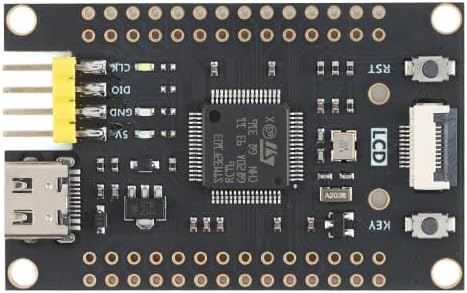
Малюнок 3.1: Верх view of the STM32F103RCT6 Core Board. This image displays the main components including the STM32F103RCT6 microcontroller, the USB Type-C port for power and communication, the SPI LCD interface, and various pin headers for I/O and debugging.
3.2. Powering the Board
The core board can be powered via two methods:
- USB Type-C: Connect a standard USB Type-C cable from your computer or a 5V USB power adapter to the Type-C port on the board. This provides both power and a communication interface.
- 5V Pin Header: Alternatively, provide a stable 5V power supply to the designated 5V pin on the board's pin headers. Ensure correct polarity.
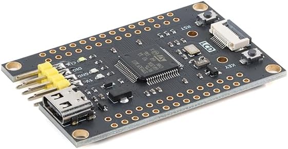
Рисунок 3.2: Кутовий view of the STM32F103RCT6 Core Board. This perspective shows the board's compact form factor and provides a clearer view of the USB Type-C port and the double-row pin headers.
3.3. Підключення периферійних пристроїв
- SPI LCD: Connect compatible SPI LCD modules directly to the FPC 10P, 0.5mm spacing LCD interface.
- SWD Debugger: Utilize the 2*4P pin arrangement to connect an SWD debugger for program uploading and debugging.
- Послідовний порт: The same 2*4P pin arrangement also provides access to the serial port for communication and printing debug information.
- GPIO: Connect external sensors, actuators, and other components to the 45 available IO ports via the pin headers.
4. Інструкція з експлуатації
4.1. Налаштування середовища розробки
To begin development, install an appropriate Integrated Development Environment (IDE) such as Keil MDK, STM32CubeIDE, or PlatformIO. Ensure you have the necessary toolchains and drivers for STM32 microcontrollers installed on your computer.
4.2. Програмування мікроконтролера
Programs can be uploaded to the STM32F103RCT6 via the SWD interface using an ST-Link debugger or similar. Alternatively, the built-in bootloader can be used with a serial connection for programming, typically requiring specific boot mode pin configurations.
4.3. Using the User Buttons and LEDs
- Кнопка скидання: Pressing this button will restart the microcontroller, executing the program from the beginning.
- Кнопка користувача: This button is programmable and can be assigned various functions within your application.
- User LEDs: The two onboard LEDs are programmable and can be used for status indication, debugging, or as part of your application's output.
5. Pinout Diagram and Components
The board features clearly labeled pin headers providing access to the microcontroller's GPIOs, power lines, and communication interfaces. Refer to the images below for a visual guide to the board's layout and pin assignments.
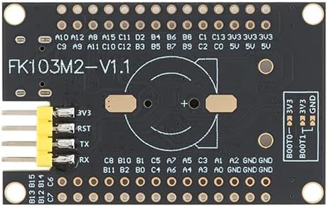
Малюнок 5.1: Нижня частина view of the STM32F103RCT6 Core Board. This image highlights the pin labels for various GPIOs, power pins (3V3, GND), and the solder pad for the CR1220 RTC battery. The "FK103M2-V1.1" board version is also visible.
5.1. Pin Header Overview
The board provides two rows of pin headers on each side, exposing a total of 45 IO ports. These include general-purpose input/output pins, analog-to-digital converter (ADC) inputs, timer outputs, and various communication interfaces like I2C, SPI, and UART.
5.2. RTC Battery Holder
A solder pad is reserved for a CR1220 coin cell battery, which can be installed to power the Real-Time Clock (RTC) for timekeeping functions even when the main power is off.

Figure 5.2: STM32F103RCT6 Core Board dimensions. This image shows the physical dimensions of the board, measuring approximately 53mm in length and 33mm in width, which is useful for enclosure design and project planning.
6. Технічні характеристики
| Особливість | Деталь |
|---|---|
| Мікроконтролер | STM32F103RCT6 |
| Основна частота | 72 МГц |
| Флеш-пам'ять | 256 КБ |
| SRAM | 48 КБ |
| Порти IO | 45 |
| РК-інтерфейс | SPI driver, FPC 10P, 0.5mm spacing |
| Debugging Interface | SWD, Serial Port (via 2*4P pin arrangement) |
| Джерело живлення | 5V or USB (Type-C) |
| Main Clock Crystal | 8 МГц |
| Кристал RTC | 32.768 кГц |
| Тримач батареї RTC | Reserved solder pad for CR1220 |
| Робоча температура | -40°C до 85°C |
| Розміри (прибл.) | 53 мм х 33 мм |
| Вага товару | 1 унції |
7. Вирішення проблем
- Плата не вмикається:
- Ensure the USB Type-C cable is securely connected and providing power.
- If using the 5V pin header, verify the power supply is stable and correctly connected with proper polarity.
- Check for any visible damage to the board or components.
- Program not uploading:
- Verify that your SWD debugger or serial programmer is correctly connected to the board's 2*4P pin headers.
- Ensure the correct drivers for your debugger are installed on your computer.
- Check your IDE settings for the correct target device (STM32F103RCT6) and programming method.
- Confirm the boot mode pins are correctly configured if using serial programming.
- LCD not displaying:
- Ensure the FPC ribbon cable for the LCD is correctly inserted into the SPI LCD interface with the correct orientation.
- Verify that your code correctly initializes and drives the SPI LCD module.
- Check for compatibility between your LCD module and the board's SPI interface.
- Неочікувана поведінка:
- Review your code for logical errors.
- Check all external connections for shorts or loose wires.
- Ensure power supply is stable and sufficient for all connected peripherals.
- Consult the STM32F103RCT6 datasheet and reference manuals for detailed information on peripheral configuration.
8. Технічне обслуговування
- Прибирання: Keep the board clean and free from dust and debris. Use a soft, dry brush or compressed air for cleaning. Avoid using liquids.
- Зберігання: Store the board in an anti-static bag when not in use to prevent electrostatic discharge (ESD) damage. Keep it in a dry environment away from extreme temperatures.
- Обробка: Always handle the board by its edges to minimize contact with components and prevent ESD.
- Батарея RTC: If an RTC battery is installed, replace it when necessary (typically every few years, depending on usage and battery type) to maintain accurate timekeeping.
9. Гарантія та підтримка
For warranty information and technical support, please refer to the official EC Buying webсайт або зверніться безпосередньо до служби підтримки клієнтів. Зберігайте чек про покупку як підтвердження покупки.
Note: Unauthorized modifications or improper use of the product may void the warranty.