
1. Вступ
The WANLUTECH multi-function OTDR is a handheld device designed for evaluating FTTx and access network construction and maintenance. It identifies fiber breakpoints, measures cable length, and calculates relative optical power losses. This device displays the power of the returned signal related to distance, providing crucial information to confirm the transmission quality of a fiber optic link. It is widely used in the maintenance, construction, and monitoring of cable lines, capable of measuring optical fiber length, transmission attenuation, splice attenuation, and failure locations.
2. Інформація про безпеку
Будь ласка, прочитайте та зрозумійте всі інструкції з безпеки перед використанням пристрою. Недотримання цих інструкцій може призвести до травмування або пошкодження пристрою.
- Лазерна безпека: This device contains a laser. Do not stare directly into the optical output ports or expose eyes to the laser light. Always use appropriate eye protection when working with fiber optic equipment.
- Безпека батареї: Use only the specified battery type and charger. Do not disassemble, crush, or expose the battery to extreme temperatures.
- Умови навколишнього середовища: Operate the device within the specified temperature and humidity ranges. Avoid exposure to dust, moisture, and corrosive substances.
- Технічне обслуговування: Refer all servicing to qualified personnel. Do not attempt to repair the device yourself.
3. Налаштування
3.1 Initial Battery Preparation
Before using the tester for the first time, open the battery cover and remove the paper piece isolating the battery. This ensures proper electrical contact and allows the device to power on.
3.2 Пристрій закінчивсяview
Familiarize yourself with the ports and controls of the WANLUTECH MOT-65 OTDR Fiber Tester.

малюнок 3.2.1: Front and Back Panel Layout of the WANLUTECH MOT-65 OTDR Fiber Tester. The top panel includes the DC5V/2A power output, LED lamp, Network testing port, PSE/PoE voltage measurement port, OTDR/LS port, VFL port, OPM port, and Power button. The bottom panel includes the 12V1A input, Reset button, and UTP/Cable tracer port.
Top Panel Features:
- Вихідна потужність DC5V/2A: Provides power to external devices.
- Світлодіод Lamp: Вбудоване джерело світла для освітлення.
- Network Testing Port (LAN/RJ45 TDR): Used for network cable tests.
- PSE/PoE Voltage Measurement (PSE IN): Measures Power over Ethernet (PoE) switch or PSE power supply voltage.
- OTDR/LS Port: Optical Time Domain Reflectometer and Light Source output.
- VFL Port: Visual Fault Locator output.
- OPM Port: Optical Power Meter input.
- Кнопка живлення: Вмикає/вимикає пристрій.
Bottom Panel Features:
- 12V1A Input: Вхід живлення для заряджання пристрою.
- Кнопка скидання: Скидає налаштування пристрою.
- UTP / Cable Tracer Port: Used for UTP cable testing and cable tracing functions.
4. Інструкція з експлуатації
4.1 Випробування рефлектометром
The OTDR function is used to characterize optical fibers. The MOT-65 supports a 1610nm wavelength with a 28dB dynamic range and live testing at 1310/1490/1550/1577nm.

малюнок 4.1.1: OTDR Quick Setup, Parameters Set Mode, and Event Map Interface. The Quick Setup allows for rapid configuration of wavelength, distance range, pulse width, and measurement duration. The Parameters Set mode offers advanced control over various testing parameters for more precise results.
4.1.1 Quick Setup Mode
This mode allows for quick configuration of essential OTDR parameters:
- Set wavelength.
- Define distance range.
- Adjust pulse width.
- Specify measurement duration.
4.1.2 Parameters Set Mode
For professional technicians requiring precise control, this mode allows setting:
- Wavelength (e.g., 1610nm).
- Distance range.
- Pulse width.
- Режим вимірювання.
- IOR (Index of Refraction).
- Non-reflection threshold.
- End threshold.
4.2 Карта подій
The Event Map visualizes the results of fiber optic link inspections, presenting information such as link length, connector type, fusion points, or breakpoints in a graphical format for easier understanding.
малюнок 4.2.1: Event Map Display. This interface shows a simplified view of fiber events along the link. Icons represent different event types.
Event Map Icons:
- Початкова подія: Represents the starting point of the link.
- Рефлексія Подія: Indicates a connector or reflection event, shown as a peak signal.
- Подія без відображення: Denotes a fusion point or optical fiber bending, shown as a drop of optical power.
- Кінцева подія: Marks the terminal of the fiber, with reflection peak indicating a normal end.
- End Event (Fracture): Indicates an optical fiber bending or fracture at the end of the link.
The Event Blind Zone is ≤1.6m, and the Attenuation Blind Zone is ≤8m.
4.3 Вимірювач оптичної потужності (OPM)
The OPM measures the optical power of a fiber optic signal. Connect the measured fiber to the OPM port. The device supports calibrated wavelengths of 850/1300/1310/1490/1550/1625nm with a measurement range of -70 to +10 dBm.

малюнок 4.3.1: Optical Power Meter (OPM) Interface. This screen displays the measured optical power in dBm and allows selection of calibrated wavelengths.
4.4 Візуальний локатор несправностей (VFL)
The VFL is used to determine fiber continuity and locate faults. It emits a visible red laser light (650nm wavelength) with a maximum test range of 8 KM. Connect the fiber to the VFL port.
малюнок 4.4.1: Visual Fault Locator (VFL) Interface. This screen shows the VFL status and allows activation of steady or blinking modes.
4.5 Light Source (LS)
The Light Source function connects to the OTDR/LS port and is used for engineering and maintenance of optical fiber communication and CATV. It supports CW (Continuous Wave) mode and modulated frequencies of 270 Hz, 330 Hz, 1 kHz, and 2 kHz.
малюнок 4.5.1: Light Source (LS) Interface. This screen allows selection of wavelength, mode (CW or modulated frequencies), and power level.
4.6 Optical Loss Test (OLS)
The OLS function is used to test the insertion loss of optical passive devices. Calibrate the OTDR/LS port and OPM port with a short fiber optic patch cable, then proceed with the test.
малюнок 4.6.1: Optical Loss Test (OLS) Interface. This screen displays the optical power meter readings and allows for parameter setting and connection diagram viewінж.
4.7 Network Test Tools
The device includes built-in professional network testing tools.

малюнок 4.7.1: Network Test Tools Interface. This section provides access to various network diagnostic functions including Ping, IP Scan, DHCP Server, PPPOE, Trace Route, Port Flash, LLDP, and Link Monitor.
4.7.1 Тест Ping
Verifies connectivity to a host on an IP network.
4.7.2 IP Scan
Scans for active IP addresses within a specified range.
4.7.3 FTP File управління
Дозволяє file transfer and management using FTP. To use, ensure an SD card is inserted and enter the tester's FTP address in a computer's browser.
малюнок 4.7.2: FTP File Management Interface. This screen shows options for anonymous login, using an external SD card, and the FTP server address for accessing files.
4.7.4 Виявлення PoE
Measures PoE switch or PSE power supply voltage and cable connection status. Connect the PoE source to the PSE IN port of the OTDR tester.
малюнок 4.7.3: PoE Detection Interface. This screen displays the detected PoE voltage and cable connection status, indicating which pairs are carrying power.
4.7.5 WiFi Analyzer
Supports analyzing WiFi signal strength, channel quality, and creating WiFi hotspots. Built-in 2.4G WiFi with speeds up to 150Mbps.
малюнок 4.7.4: WiFi Analyzer Interface. This screen shows detected WiFi networks, their signal strength, channel information, and security details.
4.8 Випробування кабелів
The device offers various cable testing functionalities.
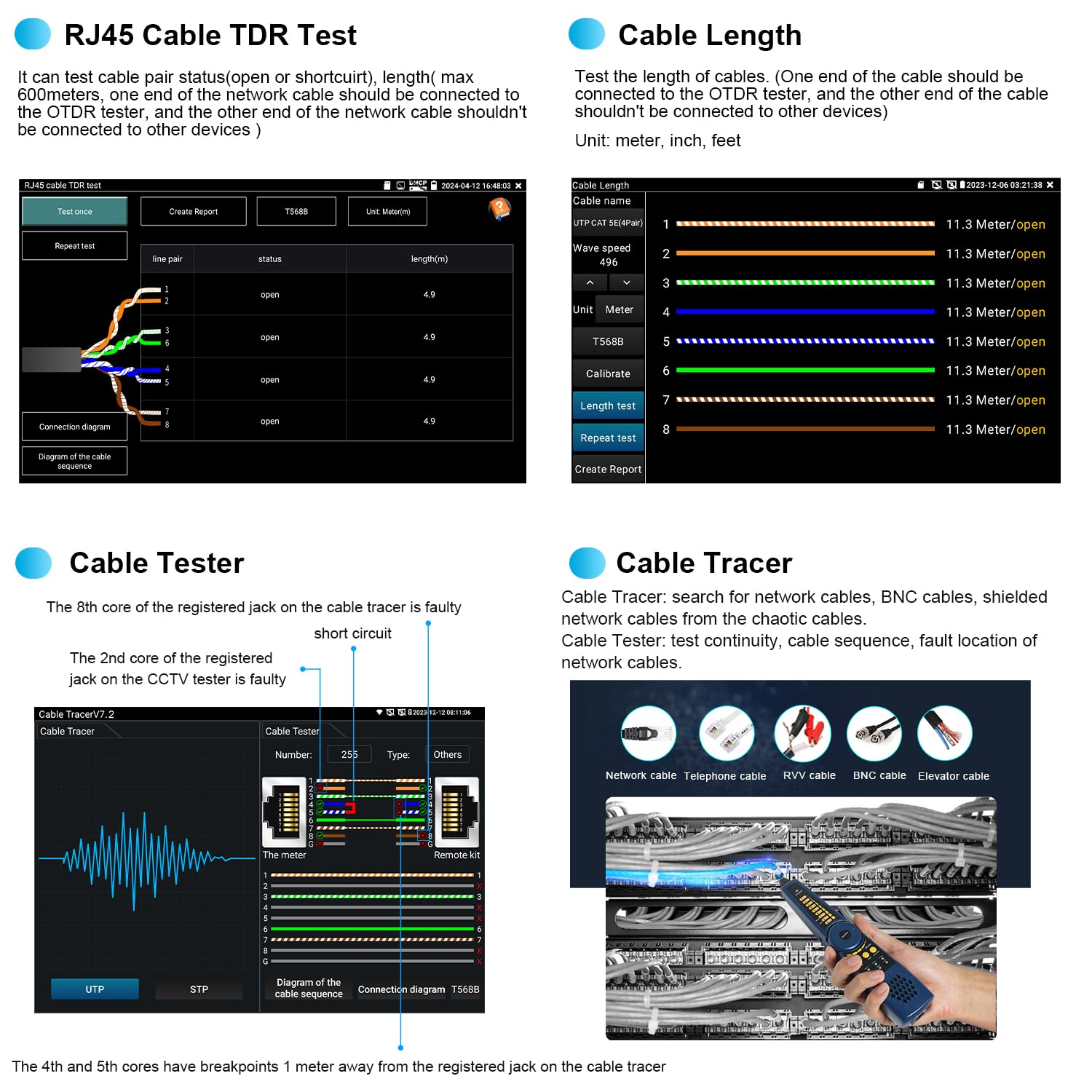
малюнок 4.8.1: Cable Testing Interfaces. This image displays the RJ45 Cable TDR Test, Cable Length measurement, Cable Tester, and Cable Tracer functions.
4.8.1 Тестування кабелю RJ45 за допомогою рефлексного датчика (TDR)
Tests the status of cable pairs (open or short circuit) and measures length up to 600 meters. The cable pair status and length are displayed on the screen.
4.8.2 Вимірювання довжини кабелю
Tests the length of cables. The other end of the cable should be connected to the OTDR tester, and the other end of the cable should not be connected to other devices. Unit can be set to meter, inch, or feet.
4.8.3 Тестер кабелю UTP
Tests the connection status of UTP cables and displays results on the screen. It supports detection of near-end, mid-end, and far-end fault points of the RJ45 cable plug.
4.8.4 Digital Cable Tracer
Searches for BNC, network, and telephone cables from cluttered bundles. It can also search shielded cables.
4.9 Керування даними
The device provides tools for managing test data and reports.

малюнок 4.9.1: Data Management Interfaces. This image shows the Test Report, File Setting, and File Management screens.
4.9.1 Протокол випробувань
Save one or more curve trajectories and a list of events, parameters, fiber chains, and rulers corresponding to the curves. Test reports are available in EXCEL and PDF formats. The SOR standard file формат підтримується.
4.9.2 File Налаштування
Enable or disable automatic file naming. Select the file format (OTDR or SOR) and file name type.
4.9.3 File управління
Open selected curve files. Up to 4 curve files can be simultaneously selected for viewing and analysis. Supports zoom and move curves, and viewдеталі.
5. Технічне обслуговування
Proper maintenance ensures the longevity and accuracy of your WANLUTECH MOT-65 OTDR Fiber Tester.
- Прибирання: Regularly clean the device's screen and exterior with a soft, dry cloth. For optical ports, use specialized fiber optic cleaning tools and procedures to prevent contamination.
- Зберігання: Store the device in a cool, dry place away from direct sunlight and extreme temperatures. Use the provided tool bag for protection during transport and storage.
- Догляд за акумулятором: Charge the built-in 7.4V 5200mAh battery regularly, even if not in use, to maintain its health. Avoid fully discharging the battery for extended periods.
- Догляд за роз'ємом: Always keep optical connectors clean and capped when not in use to prevent dust and debris from affecting measurements.
6. Вирішення проблем
This section addresses common issues you might encounter with the WANLUTECH MOT-65 OTDR Fiber Tester.
| проблема | Можлива причина | Рішення |
|---|---|---|
| Пристрій не включається. | Battery not charged; battery isolation paper not removed; device fault. | Ensure battery isolation paper is removed. Charge the battery. If issue persists, contact support. |
| Slow boot-up time. | Normal operation for complex devices. | This is generally normal and not indicative of a fault. Allow the device to complete its startup sequence. |
| Inaccurate OTDR readings. | Dirty optical connectors; incorrect test parameters; fiber damage. | Clean all optical connectors. Verify test parameters (wavelength, IOR, pulse width). Inspect fiber for damage. |
| VFL light not visible or weak. | Dirty VFL port; fiber not properly connected; VFL module fault. | Clean the VFL port. Ensure fiber is securely connected. If issue persists, contact support. |
| Network test fails. | Incorrect cable connection; network configuration issues. | Verify cable connections. Check network settings (IP, gateway, DNS). |
7. Технічні характеристики
Key technical specifications for the WANLUTECH MOT-65 OTDR Fiber Tester.
| Особливість | Специфікація |
|---|---|
| Модель | ТО-65 |
| Довжина хвилі рефлектометра | 1610nm (supports 1310/1490/1550/1577nm live test) |
| Динамічний діапазон рефлектометра | 28 дБ |
| Сліпа зона подій | ≤1.6м |
| Attenuation Blind Zone | ≤8м |
| Дисплей | 5.4-дюймовий IPS сенсорний екран |
| Optical Power Meter (OPM) Wavelengths | 850/1300/1310/1490/1550/1625nm |
| OPM Measurement Range | -70~+10 дБм |
| Visual Fault Locator (VFL) Wavelength | 650 нм |
| Максимальний діапазон випробувань VFL | 8 км |
| Light Source (LS) Modes | CW/270 Гц/330 Гц/1 кГц/2 кГц |
| Довжина тесту TDR кабелю RJ45 | Макс 600 метрів |
| Акумулятор | Вбудований 7.4V 5200mAh |
| Вхідна потужність | DC12V/1A |
| Вихідна потужність | DC5V/2A |
| Порт Ethernet | One Gigabit Ethernet port, 10/100/1000Mbps adaptive |
| WiFi | Built-in 2.4G WIFI, speeds 150M |
| Роз'єми в комплекті | 1*SC/UPC, 1*FC/UPC, 1*ST/UPC, 1*LC/UPC adapter, 1*FC male-FC female adapter, 1*FC male-SC female adapter, 1*FC(male)- LC(female) adapter, 1*SC/UPC(Male)-SC/APC(Female) adapter, 1*Patch Cord(FC/UPC-FC/APC) |
| Дотримано стандартів безпеки | UL 61010-1, IEC 61010-2-030 |
8. Гарантія та підтримка
For any questions or technical assistance regarding your WANLUTECH MOT-65 OTDR Fiber Tester, please contact the manufacturer directly. We are committed to providing support and will respond to inquiries within 12 hours.
Будь ласка, зверніться до документації щодо придбання, щоб дізнатися про конкретні гарантійні умови.