
DAOKAI WE-DA-092
Інструкція користувача модуля пам'яті EEPROM I2C DAOKAI AT24C256
Model: WE-DA-092
Brand: DAOKAI
1. Вступ
This manual provides comprehensive instructions for the DAOKAI AT24C256 I2C EEPROM Memory Module. This breakout board is designed to facilitate the integration of an EEPROM (Electrically Erasable Programmable Read-Only Memory) into your electronic projects. The AT24C256 chip offers 256 kilobits (32 kilobytes) of non-volatile data storage, organized into 8192 words of 8 bits, accessible via the common I2C serial interface. It is ideal for applications requiring persistent data storage, such as configuration settings, logging, or small data tables.

Малюнок 1.1: Закінченоview of the AT24C256 I2C EEPROM Memory Module. This image shows the compact blue PCB with the AT24C256 chip in a DIP socket, along with header pins for connection and other components.
2. Вміст упаковки
Перевірте, чи всі перелічені нижче предмети входять до вашої упаковки. Якщо будь-які предмети відсутні або пошкоджені, зверніться до постачальника.
- 5 x AT24C256 I2C interface EEPROM Memory Module
- 1 x 20pin Female to Male Dupont Cable
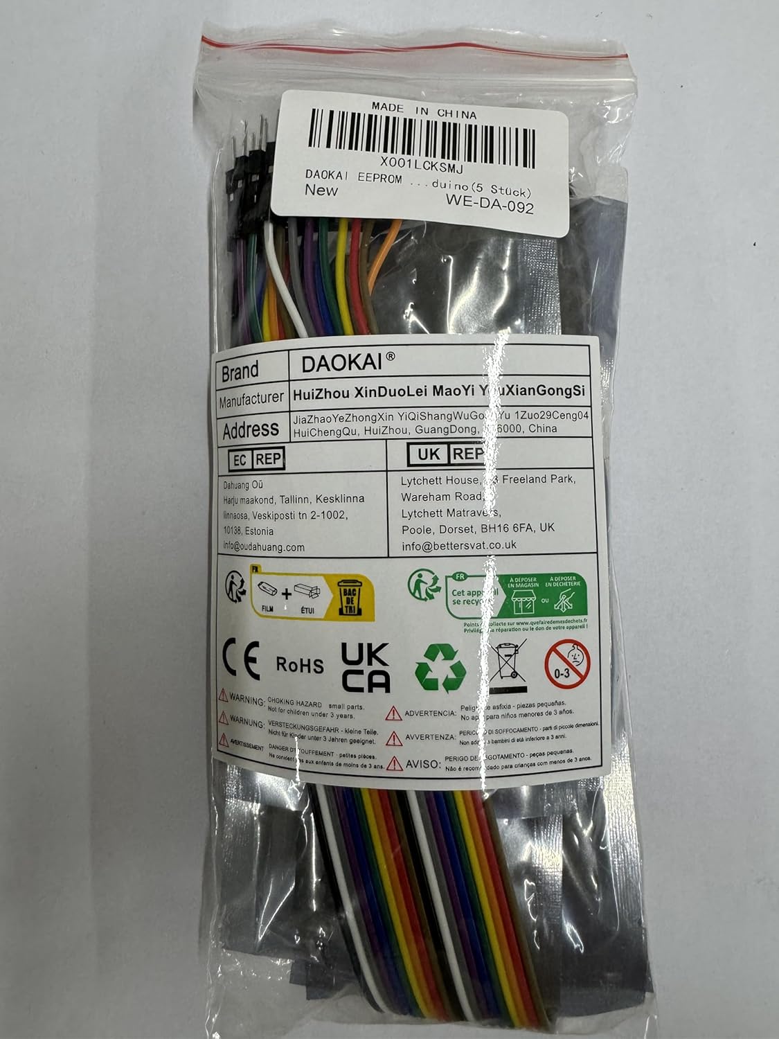
Figure 2.1: Contents of the package, showing multiple AT24C256 modules and a set of Dupont cables.
3. Характеристики та технічні характеристики продукту
3.1. Ключові характеристики
- AT24C256 Chip: Onboard 8P-chip carrier, supporting AT24C256 series chips.
- Інтерфейс I2C: Communication handled through a 2-pin I2C interface.
- Вибір адреси: I2C address can be set by A0, A1, A2 jumpers for addresses in the range of 0x50 - 0x57.
- Індикатор живлення: Onboard LED indicator for power status.
- Pull-up Resistors: Onboard pull-up resistors for I2C communications.
- Pin Accessibility: All pins are clearly labeled and led out for easy connection.
- Захист від запису: Dedicated write-protect pin (WP) with direct jumper settings.
- Ємність зберігання: 256 kilobits (32 kilobytes) of EEPROM storage.
- Компактний дизайн: 8-pin double-row in-line package, compact structure.
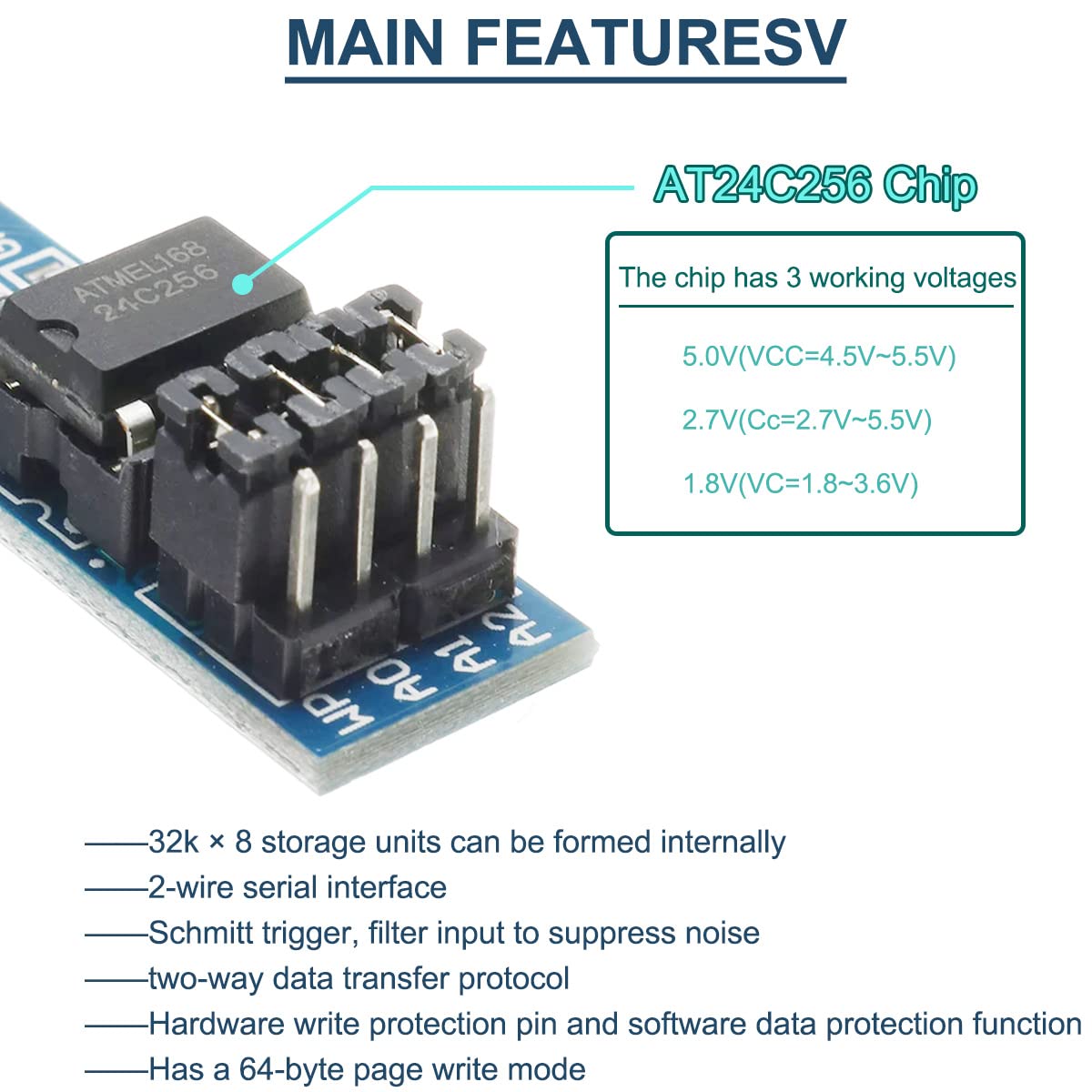
Figure 3.1: Illustration of the AT24C256 chip and its key features, including supported working voltages and internal structure details.
3.2. Технічні характеристики
| Параметр | Значення |
|---|---|
| Чіпсет | AT24C256 EEPROM |
| Ємність зберігання | 256k bits (32k bytes) |
| Інтерфейс зв'язку | I2C (Two-wire serial interface) |
| I2C Communication Address Range | 0x50 - 0x57 (configurable via A0, A1, A2) |
| Робочий випtagе (VCC) | 1.8V - 5.5V (depending on chip version) |
| Робочий струм | 5 мА (типовий) |
| Робоча температура | -55°C до 125°C |
| Pin Pitch | 2.54 мм |
| PCB Board Size | 36.5 мм x 12 мм (1.43 дюйми x 0.47 дюйми) |

Figure 3.2: Physical dimensions of the AT24C256 I2C EEPROM Memory Module, showing its length and width.
4. Pin Definition and Schematic
4.1. Визначення шпильки
The module features a standard pinout for easy integration. Understanding each pin's function is crucial for proper operation.
- А0, А1, А2: Address selection inputs. These pins are used to set the I2C slave address of the EEPROM. By connecting these pins to GND or VCC, you can select one of eight possible addresses (0x50 to 0x57). In a serial bus structure, multiple AT24C256 ICs can be connected by using different address settings. For example, if A1 is 0 when floating.
- SCL: Serial Clock Input. This pin provides the clock signal for I2C communication. The rising edge of SCL writes data to the memory, and the falling edge reads data from the memory.
- ПДР: Bidirectional Serial Data Input/Output. This pin is used for data exchange between the memory module and the microcontroller.
- WP: Write Protect Input. When this pin is connected to GND, write operations are allowed. When connected to VCC, all write memory operations are disabled, protecting the data. If not connected, the chip is internally pulled down to ground, enabling write operations by default.
- VCC: Power Supply. Connect to the positive voltage supply (e.g., 3.3V or 5V).
- GND: Ground. Connect to the common ground of your system.
- NC: Not Connected / Empty.

Figure 4.1: Detailed pinout diagram of the AT24C256 chip and its corresponding functions on the module.
4.2. Product Schematic
The following schematic illustrates the internal connections and components of the AT24C256 I2C EEPROM Memory Module. This can be useful for advanced users or for troubleshooting.

Figure 4.2: Electrical schematic of the AT24C256 module, showing the AT24C256 chip, pull-up resistors (R12, R13), and pin connections.
5. Налаштування та підключення
This section guides you through the process of connecting the AT24C256 EEPROM module to your microcontroller (e.g., Arduino).
5.1. Basic Wiring
- Підключення живлення: Підключіть VCC pin of the module to the 3.3V or 5V power supply output of your microcontroller. Connect the GND pin of the module to the ground (GND) of your microcontroller.
- I2C Connection:
- Підключіть ПДР pin of the module to the SDA (Serial Data Line) pin of your microcontroller.
- Підключіть SCL pin of the module to the SCL (Serial Clock Line) pin of your microcontroller.
- Address Selection (A0, A1, A2): These pins determine the I2C address. For a single module, you can leave them floating (which typically defaults to 0x50 if internally pulled low) or connect them to GND for 0x50. If using multiple modules on the same I2C bus, connect A0, A1, A2 to VCC or GND in different combinations to assign unique addresses (0x50 to 0x57).
- Write Protect (WP): For normal read/write operations, ensure the WP pin is connected to GND. To prevent accidental writes and protect data, connect the WP pin to VCC.
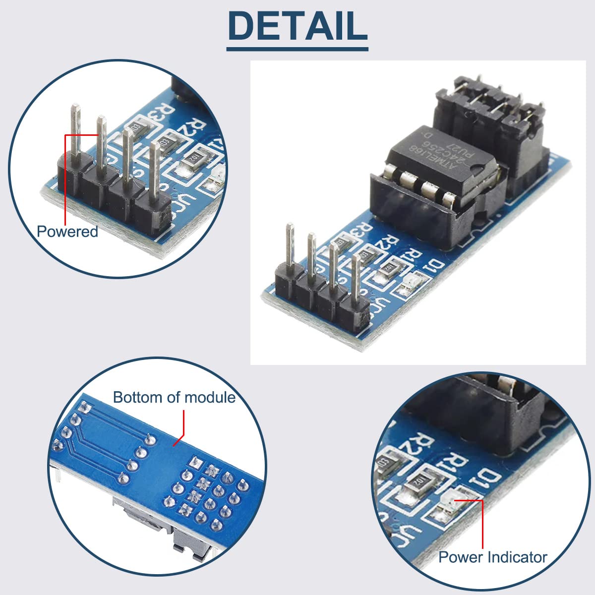
Малюнок 5.1: Збільшений план views of the module, highlighting the powered pins and the onboard power indicator LED.
5.2. Вихample Connection (Arduino)
For Arduino Uno/Nano/Mega:
- Module VCC → Arduino 5V (or 3.3V if your AT24C256 chip supports it)
- Module GND → Arduino GND
- Module SDA → Arduino A4 (SDA)
- Module SCL → Arduino A5 (SCL)
- Module A0, A1, A2 → Connect to GND for default address 0x50, or configure as needed.
- Module WP → Connect to GND for read/write operations.
6. Operating Principles and Programming
The AT24C256 module communicates using the I2C protocol. This section outlines the basic principles for interacting with the EEPROM.
6.1. I2C Communication Basics
The I2C protocol is a two-wire serial communication bus. It operates with a master (your microcontroller) and one or more slaves (the EEPROM module).
- Адреса раба: The AT24C256 has a base I2C address of 0x50. The A0, A1, A2 pins allow you to modify the last three bits of this address, enabling up to 8 unique addresses (0x50 to 0x57) for multiple devices on the same bus.
- Передача даних: Data is transferred in 8-bit bytes. Each byte is followed by an Acknowledge (ACK) or Not Acknowledge (NACK) bit.
- Memory Addressing: The AT24C256 has 32,768 bytes (32KB) of memory. To access a specific byte, you send a 16-bit memory address after the device address.
6.2. Read/Write Operations
Most microcontrollers have built-in I2C (Wire) libraries that simplify communication.
- Запис даних:
- Почніть спілкування I2C.
- Send the device write address (e.g., 0x50).
- Send the 16-bit memory address (high byte then low byte) where you want to write.
- Send the data byte(s) you wish to store.
- Stop I2C communication.
Note: The AT24C256 supports page writes of up to 64 bytes. If writing more than 64 bytes, you must perform multiple page writes.
- Дані читання:
- Почніть спілкування I2C.
- Send the device write address (e.g., 0x50).
- Send the 16-bit memory address from where you want to read.
- Restart I2C communication.
- Send the device read address (e.g., 0x51).
- Read the data byte(s).
- Stop I2C communication.
7. Заявка Exampлес
The AT24C256 EEPROM module is versatile and can be used in various projects requiring non-volatile data storage.
- Configuration Storage: Store user settings, calibration data, or device configuration parameters that need to persist even after power loss.
- Реєстрація даних: Record sensor readings, event logs, or operational data in embedded systems.
- Lookup Tables: Store fixed data tables that are frequently accessed by the microcontroller.
- Bootloader Parameters: Save parameters for bootloaders or firmware updates.

Figure 7.1: An illustrative setup showing the AT24C256 module connected to an Arduino board, potentially used for storing servo motor positions or other project data.
8. Вирішення проблем
If you encounter issues with your AT24C256 EEPROM module, consider the following troubleshooting steps:
- Module Not Detected (I2C Scan Fails):
- Перевірте проводку: Ensure VCC, GND, SDA, and SCL connections are correct and secure.
- Джерело живлення: Verify the module is receiving the correct voltage (e.g., 5V or 3.3V). The onboard LED should light up if powered.
- Адреса I2C: Confirm the I2C address used in your code matches the physical A0, A1, A2 pin settings on the module.
- Pull-up Resistors: While the module has onboard pull-ups, ensure they are sufficient for your bus length and other devices. If using a long bus or many devices, external pull-ups (4.7kΩ to 10kΩ) on SDA and SCL to VCC might be needed.
- WP Pin: Ensure the WP pin is correctly configured (connected to GND for write operations).
- Data Corruption or Inconsistent Reads:
- Стабільність живлення: Unstable power supply can lead to data issues. Ensure a clean and stable power source.
- Timing Issues: Ensure your microcontroller's I2C clock speed is compatible with the AT24C256 (typically up to 400kHz).
- Write Cycle Time: After a write operation, the EEPROM requires a short time (typically 5ms) to complete the write cycle before it can be read or written to again. Ensure your code accounts for this delay.
- WP Pin: Double-check the WP pin status. If it's high (VCC), write operations will fail silently.
- Перегрів модуля:
- Неправильний випtage: Ensure you are not supplying a voltage higher than the maximum rated voltage for the chip (typically 5.5V).
- Короткі замикання: Check for any accidental short circuits on the module or in your wiring.
9. Технічне обслуговування та догляд
The AT24C256 EEPROM module is a robust electronic component, but proper care can extend its lifespan and ensure reliable operation.
- Обробка: Handle the module by its edges to avoid touching the electronic components, which can be sensitive to static electricity.
- Зберігання: Store the module in an anti-static bag or container when not in use, especially in dry environments.
- Середовище: Avoid exposing the module to extreme temperatures, high humidity, dust, or corrosive substances.
- Прибирання: If necessary, gently clean the PCB with a soft, dry brush or a lint-free cloth. Avoid using liquids or harsh chemicals.
- Power Off Before Connecting/Disconnecting: Always ensure power is disconnected from your circuit before connecting or disconnecting the module to prevent damage.
10. Гарантія та підтримка
Information regarding product warranty and customer support is not available in the provided product data. Please refer to the seller's or manufacturer's official website for details on warranty terms, technical support, and return policies.
For further assistance, you may contact DAOKAI customer service through their official channels.
Ask a question about this manual
Ask about setup, troubleshooting, compatibility, parts, safety, or missing instructions. Manuals+ will review the question and use this page’s manual context to help answer it.