Docooler XUH6362338938855GM
Docooler JINGSHA X99-8D3 Motherboard User Manual
Model: XUH6362338938855GM
1. Вступ і даліview
The Docooler JINGSHA X99-8D3 is a high-performance ATX gaming motherboard designed for LGA2011 V3 processors. It features four-channel DDR3 memory support, an M.2 NVME slot for high-speed storage, and multiple PCI-E expansion slots, making it suitable for demanding computing tasks and gaming setups. This manual will guide you through the installation, configuration, and maintenance of your motherboard.
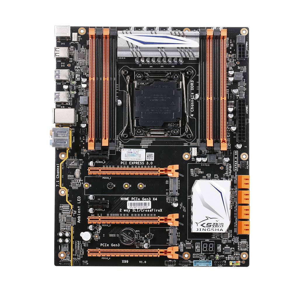
Рисунок 1.1: Зверху вниз view of the Docooler JINGSHA X99-8D3 Motherboard, showcasing its layout with CPU socket, RAM slots, and various expansion slots.
2. Ключові характеристики
- M.2 NVME Support: Equipped with an M.2 hard disk port, supporting high-speed PCI-E NVME X4 for optimal operating system and application driver performance.
- Quad-Channel DDR3 Memory: Features 8 DDR3 memory slots across 4 channels, significantly improving capacity and performance, supporting up to 256GB.
- Digital Diagnostic Card: Integrated digital diagnostic card automatically tests hardware devices to ensure proper operation and assist in troubleshooting.
- Multiple PCI-E Expansion Slots: Provides 3 PCI-E expanded slots, configurable as X16/X8 to handle various workloads and multi-GPU setups.
- Міцна конструкція: Built with a 10-layer PCB and high-quality capacitors for enhanced stability and heat resistance.

Figure 2.1: Diagram illustrating the six core technologies and features of the motherboard, including 4-channel DDR3*8, M.2 hard disk interface, digital diagnostic card, 7.1 channel audio, SATA3.0*8 interface, and Crossfire support.
3. Вміст упаковки
Будь ласка, перевірте, чи всі перелічені нижче предмети присутні у вашій упаковці:
- 1x Docooler JINGSHA X99-8D3 Motherboard
- 1x SATA кабель
- 1x I/O Baffle (Backplate)
- 1x CPU Fan Board
- A bag of screws
4. Технічні характеристики
| Особливість | Специфікація |
|---|---|
| Модель | X99-8D3 |
| Форм-фактор | ATX |
| Graphic Slot | PCIE3.0 16X*3 |
| Мережева карта | Гігабітна мережева карта |
| Аудіоканал | 7.1 канал |
| CPU Type Support | LGA2011 V3 (2629V3/2649V3/2669V3/2678V3/2696V3/2676V3/2673V3) |
| Шари друкованих плат | 10 шари |
| слот пам'яті | DDR3*8 |
| Максимальна ємність пам'яті | 256 ГБ |
| Інтерфейс SATA | SATA3.0*8, M.2 NVME |
| PS/2 Interface | Миша/клавіатура |
| Джерело живлення | 8 PIN*1, 24 PIN*1 |
| Інтерфейс USB | USB3.0*6, USB2.0*6 |
| Розширений інтерфейс | PCIE 1X*2, M.2 WIFI*1 |
| Розмір елемента | 30.2 x 24.4 см (11.89 x 9.61 дюйма) |
| Вага товару | 930.5 г (32.82 унції) |

Малюнок 4.1: Детально view of the motherboard's rear I/O panel, showing PS/2 ports, USB 2.0, USB 3.0, Gigabit Network Port, and 7.1 Audio Ports.
5. Налаштування та встановлення
Перед початком встановлення переконайтеся, що ваша система вимкнена та від’єднана від розетки. Тримайте материнську плату за краї, щоб уникнути статичної електрики.
5.1 Встановлення процесора
- Locate the LGA2011 V3 CPU socket on the motherboard.
- Gently push down the CPU retention lever and swing it open.
- Align the triangular mark on your CPU with the corresponding mark on the socket. Carefully place the CPU into the socket without forcing it.
- Закрийте важіль фіксації, щоб закріпити процесор.
- Нанесіть тонкий, рівномірний шар термопасти на верхню частину процесора.
- Install the CPU cooler according to its manufacturer's instructions, ensuring proper contact and pressure.

Малюнок 5.1: Збільшений план view of the LGA2011 V3 CPU socket on the motherboard, ready for CPU installation.
5.2 Installing RAM Modules
- Відкрийте затискачі з обох кінців слотів пам'яті DDR3.
- Зіставте виїмку на модулі оперативної пам'яті з ключем у слоті пам'яті.
- Міцно натисніть на обидва кінці модуля оперативної пам'яті, доки затискачі не зафіксуються на місці, закріпивши модуль.
- For optimal performance, install RAM modules in matching pairs across the four channels as indicated in the motherboard manual or silkscreen.

малюнок 5.2: View of the eight DDR3 RAM slots on the motherboard, showing their arrangement for quad-channel memory configuration.
5.3 Installing Storage Devices (M.2 NVME & SATA)
- M.2 NVME SSD: Locate the M.2 slot. Insert the M.2 SSD at an angle into the slot, then gently push it down and secure it with the provided screw.
- Накопичувачі SATA: Connect your SATA SSDs or HDDs to the SATA 3.0 ports using SATA data cables. Ensure the power supply SATA power connectors are also attached to the drives.

Figure 5.3: Close-up of the M.2 interface on the motherboard, highlighting its position and the PCI-E Gen3 X4 connection for high-speed data transfer.
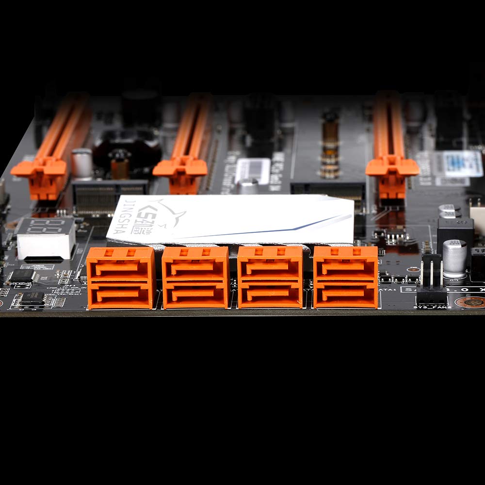
малюнок 5.4: View of the eight orange SATA 3.0 ports on the motherboard, providing ample connectivity for storage devices.
5.4 Підключення джерела живлення
- Підключіть 24-контактний роз'єм живлення ATX від блока живлення (БЖ) до відповідного порту на материнській платі.
- Connect the 8-pin CPU power connector (EPS12V) from your PSU to the 8-pin port near the CPU socket.
5.5 Встановлення плат розширення (PCIe)
- Locate the desired PCI-E 3.0 x16 or x1 slots.
- Зніміть відповідну кришку слота розширення з корпусу ПК.
- Align the expansion card with the slot and press down firmly until it is fully seated. Secure the card with a screw to the case.

Рисунок 5.5: Кутовий view of the motherboard, highlighting the three PCI Express 3.0 x16 slots and the smaller PCIe x1 slots, ready for graphics cards and other expansion cards.
6. Експлуатація материнської плати
6.1 Перше завантаження та налаштування BIOS
- Після складання всіх компонентів підключіть монітор, клавіатуру та мишу.
- Увімкніть систему. Під час початкового завантаження кілька разів натискайте DEL or F2 key (common for JINGSHA motherboards) to enter the BIOS/UEFI setup utility.
- У BIOS перевірте, чи всі встановлені компоненти (процесор, оперативна пам'ять, накопичувач) правильно визначені.
- Налаштуйте порядок завантаження, щоб надати пріоритет інсталяційному носію операційної системи (USB-накопичувачу або DVD-диску).
- Збережіть зміни та вийдіть з BIOS. Система перезавантажиться.
6.2 Встановлення операційної системи
Follow the instructions provided with your operating system (e.g., Windows, Linux) to complete the installation process. Ensure you install all necessary drivers for the motherboard's chipsets, network, audio, and other components from the manufacturer's website or included driver disc.
7. Технічне обслуговування
Правильне обслуговування гарантує довговічність та стабільну роботу вашої материнської плати.
- Видалення пилу: Регулярно очищайте материнську плату та компоненти від пилу за допомогою стисненого повітря. Перед чищенням переконайтеся, що система вимкнена та відключена від мережі.
- Оновлення BIOS: Periodically check the Docooler or JINGSHA official website for BIOS updates. BIOS updates can improve compatibility, stability, and performance. Follow update instructions carefully to avoid damaging the motherboard.
- Оновлення драйверів: Регулярно оновлюйте драйвери системи, щоб забезпечити оптимальну продуктивність та сумісність з новим програмним та апаратним забезпеченням.
- Умови навколишнього середовища: Operate the motherboard in a well-ventilated environment with stable temperature and humidity to prevent overheating and component degradation.
8. Вирішення проблем
У цьому розділі розглядаються поширені проблеми, з якими ви можете зіткнутися.
8.1 Немає живлення / Немає завантаження
- Ensure the 24-pin ATX and 8-pin CPU power connectors are securely plugged into the motherboard.
- Check if the power supply unit (PSU) is switched on and connected to a working power outlet.
- Verify that the front panel power button cable is correctly connected to the motherboard's header.
8.2 Немає виводу на дисплей
- Ensure your graphics card (if dedicated) is properly seated in its PCI-E slot and has all necessary power cables connected.
- Check that your monitor cable is securely connected to the graphics card or motherboard (if integrated graphics are used, though X99 typically requires a dedicated GPU).
- Try reseating your RAM modules. Incorrectly seated RAM is a common cause of no display.
8.3 POST Code Display (Digital Diagnostic Card)
The motherboard is equipped with a digital diagnostic card (POST code display) that shows a two-digit code during boot-up. Refer to the motherboard's detailed technical documentation (often available on the manufacturer's website) for a list of POST codes and their meanings. This can help pinpoint the exact component causing a boot failure.

Малюнок 8.1: Збільшений план view showing the integrated digital diagnostic card (POST code display) on the motherboard, which assists in identifying hardware issues during boot.
9. Гарантія та підтримка
For warranty information and technical support, please refer to the documentation provided with your purchase or visit the official Docooler or JINGSHA webсайт. Зберігайте чек про покупку для гарантійних претензій.